Integral windup occurs in control systems when the integral component of a controller accumulates error beyond a certain limit, leading to overshoot, oscillations, or instability, especially in systems with saturating actuators.
1. What is Integral Windup?
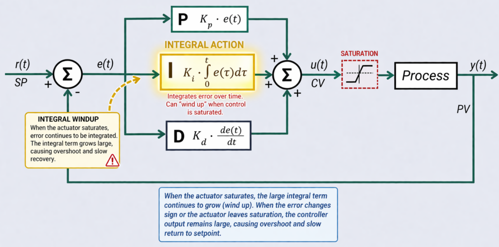
Integral windup (also known as integrator or reset windup) is a critical phenomenon in PID control systems where the integral term accumulates excessive error when the system’s actuator is saturated. This occurs when the controller demands an action beyond the physical capabilities of the actuator (e.g., commanding a valve to open beyond 100%), causing the integrator to continue “winding up” despite the actuator’s inability to respond.
- In business terms: The controller keeps “pushing harder” even when the plant cannot respond (e.g., a valve is already 100% open). It continues to accumulate error internally, leading to a massive overshoot and instability once the system can respond again.
- In engineering terms: The Integral (I) term of a PID controller continues to integrate error while the actuator is saturated (at 0% or 100% limit). When the process variable finally moves, the stored integral causes overshoot and oscillation.
- Visual Analogy: Imagine winding a spring tightly – even after the obstacle is removed, the stored energy causes the system to overshoot before the spring can unwind. This is exactly what happens with integral windup: the controller stores excessive corrective action that must be “unwound” later.
Why It Matters Financially
- Production Loss: Longer recovery times after disturbances; off-spec product.
- Energy Waste: 5–15% increase from oscillations (repeated heating/cooling, over-pumping).
- Equipment Wear: Premature valve/actuator fatigue; each oscillation cycle increases wear.
- Operator Load: Frequent manual interventions and reduced confidence in automation.
Where It Commonly Appears (High-Risk Loops)
- Tank Level Control (integrating systems) – Highly vulnerable.
- Furnace Temperature Loops – Long dead time, delayed feedback.
- Flow Control with undersized valves or pumps at max capacity.
- VFD-driven systems at speed or torque limits.
- Batch Processes with large setpoint jumps.
Observable Symptoms (No Theory Needed)
- Controller output stuck at 0% or 100% for long periods.
- Large overshoot after the process finally responds.
- Oscillations after setpoint changes or disturbances.
- Slow recovery to stable operation.
- Operators frequently switch to manual.
The Windup Mechanism: How It Works
The windup process occurs in two distinct phases:
- Windup Phase: During actuator saturation, the error remains large because the process variable cannot reach the setpoint. The integrator continues accumulating this error, building up excessive corrective action.
- Unwind Phase: When the process variable finally approaches the setpoint, the oversized integral term must decrease from its excessive value, causing significant overshoot, sluggish recovery, or sustained oscillations.
Key Insight: Windup stems from the fundamental disconnect between the controller’s mathematical calculations and the actuator’s physical limitations.
Causes and Consequences of Integral Windup
Primary Causes
| Cause | Description | Impact |
|---|---|---|
| Actuator Saturation | Physical limits (0-100% valve position) prevent the manipulated variable from responding | Primary trigger for windup |
| Large Setpoint Changes | Rapid SP changes create sudden error spikes, accelerating integrator accumulation | Causes rapid windup before process can react |
| External Disturbances | Unmeasured disturbances (load changes) overwhelm the controller | Forces actuator to saturation limits |
Root Causes (Practical Diagnosis)
| Cause | Description |
|---|---|
| Actuator Saturation | Valve too small, pump at max capacity, heater fully ON (most common). |
| Poor Tuning | Integral gain too aggressive; no consideration of dead time. |
| Process Design | Undersized equipment; slow dynamics not accounted for. |
| Operator Behavior | Large setpoint jumps; frequent manual/auto switching. |
| Control Architecture | No anti-windup logic; poor cascade design. |
Performance Impacts
Integral windup directly affects critical control system metrics:
- Increased Overshoot: Excessive integral action drives the process variable beyond the setpoint
- Extended Settling Time: The system takes longer to stabilize due to the “unwinding” process
- Oscillatory Behavior: Can lead to sustained oscillations around the setpoint
- Real-World Consequences: Reduced product quality, increased equipment wear, potential safety risks in critical processes
Comprehensive Anti-Windup Strategies
Core Prevention Methods
1. Integrator Clamping (Conditional Integration)
Principle: Freeze the integrator when the output saturates
Implementation:
// Calculate provisional output
error = setpoint - process_variable;
proportional = Kp * error;
integral = integral + (Ki * error * dt);
output = proportional + integral;

// Apply clamping when saturated
if (output > output_max) {
    output = output_max;
    integral = integral - (Ki * error * dt); // Reverse integration
} else if (output < output_min) {
    output = output_min;
    integral = integral - (Ki * error * dt); // Reverse integration
}
2. Back-Calculation
Principle: Calculate the difference between controller output and actual actuator position, then feed this back to adjust the integrator
Advantage: More sophisticated than simple clamping; automatically “unwinds” the integrator
Implementation: Uses anti-windup gain (Kaw) to regulate feedback correction
3. External Reset Feedback (ERF)
Principle: Dynamically reset the integrator using direct feedback from the actuator’s actual position
Benefit: Keeps controller’s internal state aligned with physical reality
4. Setpoint Rate Limiting
Principle: Gradually ramp large setpoint changes to prevent abrupt integrator spikes
Application: Essential for processes with large setpoint changes
6. Anti-Windup Strategies (Most Practical)
| Strategy | Best For | Pros | Cons |
|---|---|---|---|
| Integral Clamping | Fast loops (Pressure/Flow) | Simple, stops integration at limits | Can cause small offset |
| Back-Calculation | Cascade, Temperature, Batch | Smooth recovery, minimal overshoot | Requires tuning of feedback gain |
| Conditional Integration | Batch, Slow Temperature, Level | Robust, integrates only when not saturated | Requires logic to enable/disable |
| Setpoint Ramping | Large vessels, Furnaces, Batch | Prevents large initial error | Slower response to setpoint |
| Cascade Control | Flow-Pressure, Fast + Slow loops | Powerful, prevents outer loop windup | More complex design |
Decision Table for Loop Types:
| Strategy | Fast Pressure | Slow Temperature | Level (Integrating) | Batch |
|---|---|---|---|---|
| Clamping | ✓ | ✓ | ✓✓ | ✓ |
| Back-calculation | ✓✓ | ✓✓ | ✓✓ | ✓✓ |
| Conditional Integration | ✓ | ✓✓ | ✓✓ | ✓✓ |
| Setpoint Ramping | ✓ | ✓✓ | ✓ | ✓✓ |
| Cascade | ✓✓ | ✓✓ | ✗ | ✓ |
(✓✓ = highly recommended)
Implementation in Common Platforms
- Siemens (TIA Portal): Use
PID_Compactblock; setConfig.OutputUpperLimit/LowerLimitfor built-in anti-windup. - Allen-Bradley (Logix): Use
PIDEinstruction withWindupHIn/WindupLInflags and output limits. - Schneider Electric: PID function blocks support saturation handling; implement back-calculation if native block lacks it.
- General Rule: Always enable manufacturer’s built-in anti-windup first. Set output limits to match physical actuator limits (e.g., 91% for a 55Hz VFD max).
8. Key Engineering Design Patterns
- Design for Saturation Awareness: Always define Min/Max output based on physical actuator limits.
- Use Cascade Control: Outer loop (slow) commands inner loop (fast) to prevent windup.
- Setpoint Management: Ramp all large setpoint changes (especially for temperature and batch processes).
- Fail-Safe Integration: Reset or hold the integrator on mode change, interlock trip, or manual/auto transfer (bumpless transfer).
Summary Checklist for Plant Teams
| Symptom | Windup Likely? | Immediate Action (Shift) | Permanent Fix (Engineering) |
|---|---|---|---|
| Output stuck at 100% | Yes | Reduce setpoint, check for blockages | Add anti-windup (clamping/back-calc) |
| Large overshoot after recovery | Yes | Put loop in manual, stabilize | Tune integral gain, enable anti-windup |
| Oscillations after setpoint change | Yes | Damp response, reduce setpoint step | Add setpoint ramping, back-calculation |
| Slow recovery after disturbance | Yes | Operator intervention | Redesign loop, add conditional integration |
| Operators frequently go manual | High probability | Log events, review trends | Audit loop, add saturation alarm on HMI |
Advanced Control Structures
I-PD Controller
Alternative Approach: Use integral action on error, but proportional and derivative actions only on process variable
Benefit: Eliminates overshoot from setpoint changes by avoiding sudden “proportional kick”
Mechanism:
- During saturation (e.g., a valve stuck fully open), the actuator cannot correct the error, but the integrator keeps accumulating the error.
- When the process variable (PV) finally nears the setpoint (SP), the oversized integrator causes overshoot or oscillations due to its stored “excess” correction.
Vendor-Specific Implementations
Siemens FB41 PID Controller
Built-in Anti-Windup Features:
- Integrator Limits:
I_ITLVALsets maximum/minimum integrator outputs - Integrator Enable:
I_ITL_ONenforces clamping when limits are reached - Integrator Freeze:
INT_HOLDstops integration during startups or uncontrollable errors
Advanced Options:
- Use Siemens’ Modular PID library for back-calculation methods
- Custom function blocks for External Reset Feedback
Allen Bradley PIDE Controller
Basic Protection:
- Windup Flags:
WindupHIn/WindupLInfreeze integration during output saturation - Output Limits: Configure high/low MV bounds to trigger clamping
Advanced Implementation:
- External Reset Feedback: Custom logic to reset integrator using actuator feedback
- Conditional Resets: Disable/re-enable PIDE or reset integrator when PV nears SP
- Startup Logic: Delay PIDE activation until PV is near SP to avoid initial windup
Caution: Frequent integrator resets can destabilize the loop; use judiciously
Implementation Best Practices
Process-Aware Design
- Monitor Actuator Saturation: Implement valve position feedback or MV tracking to detect limits
- Process-Specific Tuning: Balance integral action based on process dynamics – slower processes often require lower integral gains
- Hierarchical Approach:
- Use clamping for basic protection
- Implement back-calculation/ERF for processes prone to prolonged saturation
- Consider setpoint limiting for systems with large SP changes
Validation and Testing
- Simulate Worst-Case Scenarios: Test under large setpoint changes and significant disturbances
- Gradual Commissioning: Implement anti-windup logic in stages, verifying each step
- Performance Monitoring: Track overshoot, settling time, and oscillation metrics
Frequently Asked Questions
Q: Doesn’t limiting the integrator hurt controller performance?
A: No. When the output is saturated, the integrator’s action is ineffective and only causes harm. Preventing windup during saturation actually improves performance when the process variable approaches the setpoint.
Q: Can proper tuning alone eliminate windup?
A: No. While reducing integral gain can minimize windup severity, it cannot eliminate windup caused by physical actuator saturation. Anti-windup mechanisms are necessary for complete protection.
Q: When should I use advanced methods like back-calculation vs. simple clamping?
A: Use clamping for most applications. Reserve back-calculation for processes with frequent or prolonged saturation periods, or where precise control during saturation recovery is critical.
Conclusion
Integral windup remains a fundamental challenge in PID control, but modern strategies provide effective solutions. The key takeaways are:
- Windup arises from the integrator-actuator disconnect during saturation conditions
- Prevention requires both controller logic (anti-windup mechanisms) and process awareness (understanding actuator limits and process dynamics)
- Vendor-specific tools provide basic protection, while advanced processes may require custom implementation
- Always tailor solutions to your specific process requirements and controller capabilities
By implementing the appropriate anti-windup strategies and following best practices, control engineers can significantly improve system performance, reduce overshoot, and ensure stable operation across all operating conditions.
10. Business Impact: Simple Estimation
Annual Cost of Windup ≈
(Recovery Time in hours × Hourly Margin)
- (Extra Valve Strokes × Maintenance Cost per Stroke)
- (Energy Waste % × Annual Energy Cost)
Typical Numbers:
- Production Loss: One hour of instability in a $5,000/hr plant = $5,000 direct loss.
- Energy Waste: 2–5% extra fuel/steam in temperature loops.
- Valve Wear: Each extra 10,000 strokes shortens life by ~1 year ($8k–$15k replacement).
- Mid-size plant total: $150k–$750k per year in combined losses.
Final Takeaway
“Most plants don’t have a hardware problem — they have a control strategy problem.”
Engage our on-demand Micro-consulting Services on PID Controller
“We don’t ask you to believe us. For $950, we prove our value on one loop. You get a report that either confirms your suspicions or shows you something new. If you like it, buy more. If not, you’re out less than a dinner for two.”